Mr. Midkiff's 2013-14 Autocad Drawrings
This is a blog dedicated to the LaSalle Autocad class.
Thursday, May 14, 2015
Thursday, April 16, 2015
3d Castle Baby!!
Your next project is to build a castle in your 3d program of choice, within reason. I want you to first include the two sentence descriptions assignment from moodle before you start building anything. You can do this in Microsoft word. I will include the moodle assignment at the bottom of this post. I don't want you to design a floor plan in autocad first but you are more than welcome to. You will have four classes to build the castle and I want you to include in your building everything that I asked you to write two sentences about.
You will have to build this castle between 20,000 and 25,000 square feet, I will take off major points if this is not accomplished. So here is the moodle post:
I want you to write two sentences (explaining what the piece of the castle is and why it is important to the anatomy of a castle) about each of the following pieces to a castle:
1.gateway
2.drawbridge
3.upper,middle and lower bailey
4.fore building
5.tower
6.moat
7.turret
8.curtain wall
9.keep
Use pictures from the Internet to reference and will be graded on your creativity.
Wednesday, March 25, 2015
3d Restaurant
When you are finished drawing your floor plan in CAD you will import your drawing into sketchup or 3ds max. You do this by opening sketchup/3ds max and going to file>import> and change the "files of type" to CAD and import. If you do not have the CAD option in the "files of type" box then tell me and I will ask you to email me your CAD file and I will embed it into a sketchup file and email it to you. I want you to import your cad drawing into sketchup two times. The first CAD file you will draw without ceilings. You will however draw all of the walls, the floors, the windows, all of the furniture, ovens, shelves, freezer, tables, chairs, bar, stools etc. etc. Everything that was expected to be in the CAD drawing will be expected to be included in the sketchup drawing. The second CAD file that you will include in the same drawing is to be be used to create the outside, or 3d elevation drawing of the building; meaning create the outside of the building including a roof and windows and doors. In this drawing you will not be expected to draw anything on the inside. I also want you to create a giant sign that will be placed on the out side of your building; a sign that you might be able to see from the highway. You will have three classes to do this in including today. No late projects will be accepted without a 10 point deduction for every day it's late unless you have a doctor's note.
Friday, March 13, 2015
Restaurant Project
A1 assigned 3/13
B8 assigned 3/16
Restaurant Project: 2 part project
Part 1: Autocad floor plan
Objective: To create a unique idea for a restaurant and design the floor plan in Autocad.
Directions: Come up with your own idea for a restaurant that you are going to create (For instance my idea is a restaurant aimed at the lower middle class working stiffs of the world called Large Marge's Cigar Burgers). Once you have a good idea for a restaurant you will build/ design the floor plan in Autocad. You will need to create a one story building somewhere between 3000 square feet and 5000 square feet. All walls, doorways, windows, rooms etc. must include dimensions that I can easily interpret. All exterior walls must be 1' thick, interior walls must be 6" thick. All doorways are 30" wide and doors are 2" thick. You must include windows as well; for every 20' of wall you must include at least 1 window. There are no limits on how many windows you have but they cannot be any longer than 6' per window. Make sure that walkways between rows of tables are at least 3' wide. Don't forget to switch into architectural units by typing"units" and switching from decimal. Also you will need to switch the dimension units to architectural. To do this, click on the dimension tab, choose Dimension Style, click the modify button, click on the TEXT tab at the top of the window and change the Text Height to 2' , then click on the Primary Units tab at the top of the window and change the unit format to Architectural.
You must include:
1.) Kitchen that has (label the kitchen with 1' text)
A.) Oven(s)
B.) Sink(s)
C.) Grill Area
D.) Walk-in Freezer(s)
E.) Storage Room
F.) Cabinets
G.) Break Room
H.) Refrigerator(s)
2.) Boss' Office that has (label the Office with 1' text)
A.) Desk
B.) Filing Cabinet
C.) Chair
E.) Plant
3.) Checkout Counter that has (label the Checkout Area with 1' text)
A.) Cash Register
B.) Gumball/ candy machine
C.) Bench so husbands have a place to wait on their wives who are busy talking to people.
4.) Dining Area that has (label the Dining Area with 1' text)
A.) 15 tables (at least)
B.) 4 chairs per table
C.) Waiting area for people to wait on tables to be ready
D.) Host/Hostess desk/area (does not have to include a desk)
E.) Men's and Women's (label the bath rooms with 1' text)
E.) Men's and Women's (label the bath rooms with 1' text)
Friday, January 30, 2015
New project
We will be designing homestyler.com which I will go over with you on the big screen. Use the floor plan that is included in the post as reference and create it on homestyler.com
Wednesday, January 14, 2015
Architectural Deezy Intro
An architectural drawing or architect's drawing is a technical drawing of a building (or building project) that falls within the definition of architecture. Architectural drawings are used by architects and others for a number of purposes: to develop a design idea into a coherent proposal, to communicate ideas and concepts, to convince clients of the merits of a design, to enable a building contractor to construct it, as a record of the completed work, and to make a record of a building that already exists.
In architecture, a floor plan is a drawing to scale, showing a view from above, of the relationships between rooms, spaces and other physical features at one level of a structure.
Dimensions are usually drawn between the walls to specify room sizes and wall lengths. Floor plans may also include details of fixtures like sinks, water heaters, furnaces, etc. Floor plans may include notes for construction to specify finishes, construction methods, or symbols for electrical items (press ctrl+2 in autocad to access the design center symbols).
An elevation is a view of a building seen from one side, a flat representation of one façade. This is the most common view used to describe the external appearance of a building. Each elevation is labelled in relation to the compass direction it faces, e.g. the north elevation of a building is the side that most closely faces north. Buildings are rarely a simple rectangular shape in plan, so a typical elevation may show all the parts of the building that are seen from a particular direction.
The first assignment of the class is to draw, out of the good old orange book, the floor plan from page 428 followed by the North and South Elevation drawings on page 429. You will have three full class blocks, or 4.5 hours, to finish these two pages.
We are going to use architectural units in these drawings, so type "units" and press enter and change the Length Type to Architectural and change the "Insertion Scale" to feet. We are also going to use a standard door size for every drawing that we do in 2d as well as 3d. The door dimensions are: Width=24'' and height=80''. The walls of the rooms inside of the house will be 6" thick. To add hatched lines, type "hatch" and press enter. Choose the type of "swatch" that matches that of the drawing and click on the button titled "Add pick points". Then click on the inside of the object(s) that you want to add hatched lines to and then press enter twice. For the outer walls of the structure we will be representing the inside with hatched lines.
An important part of these drawing is the zoom feature. These drawings will be larger than the drawings that have previously worked on. In order to get them to fit into the screen, you will need to draw the longest line of the home's perimeter; then go to VIEW>ZOOM>ALL and then zoom out with your mouse wheel.
We are going to fill in these gaps to the sides of the door as a 3" X 3" square. The doors will be represented with a width of 24" or 2'.
Ignore these dashed electrical lines, we are not going to draw those at all this year.
These symbols are windows, you are not required to draw them for this project. We will however be drawing them in future projects because they are a critical part houses, as you may or may not be aware of. You can draw them if you'd like but you do not have to.
Thursday, May 29, 2014
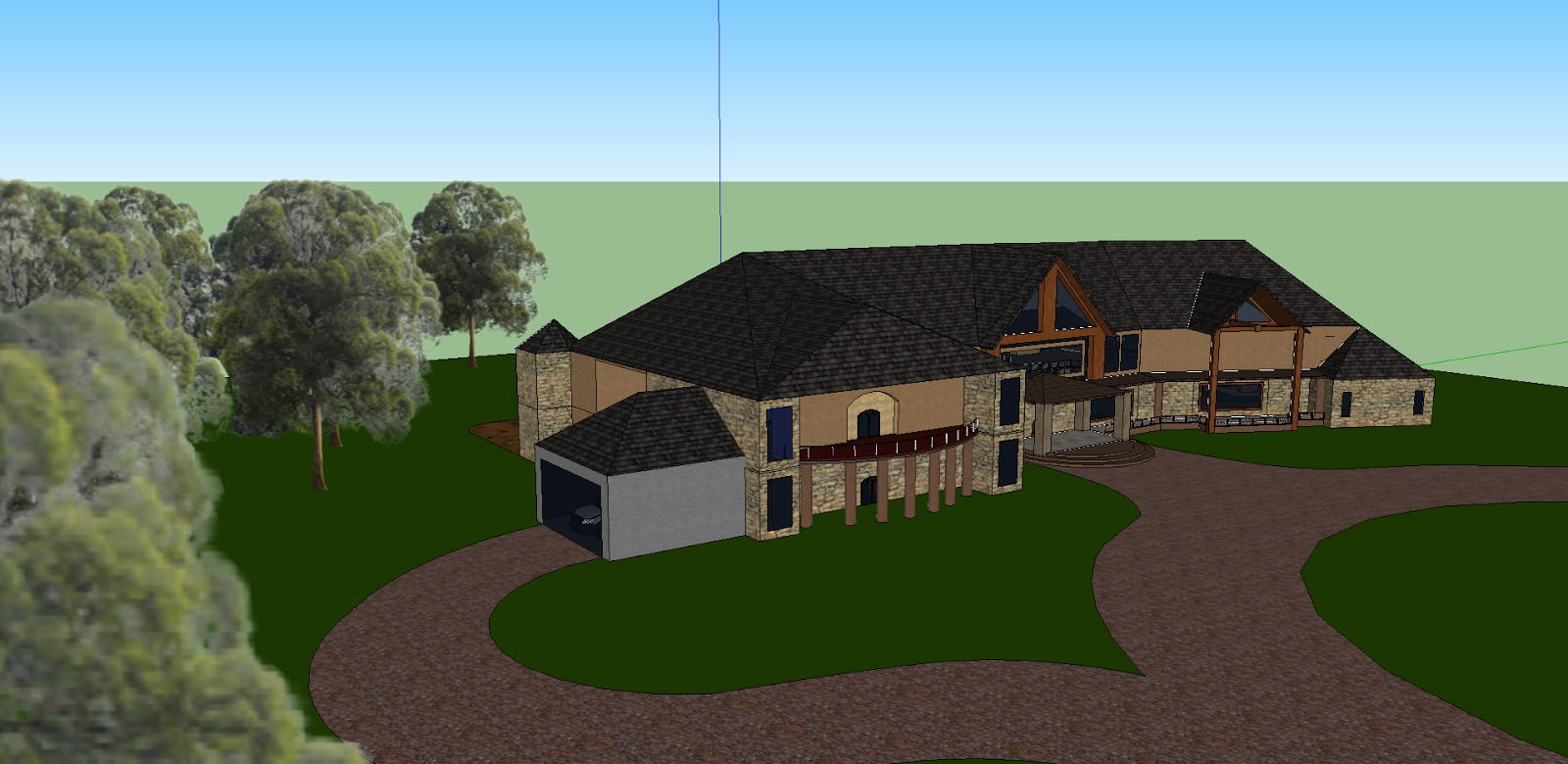
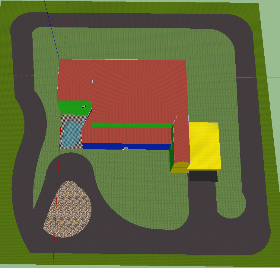
Some Architectural Designs in SketchUp
Julian Fultz
Same Dezarn
Taylor Healey
Logan Neiheisel
Devin Gallivan
Nathan Barry
Devin Gallivan
Sam Dezarn
Taylor Healey
Ian Paul
Subscribe to:
Posts (Atom)


